Case: Evolving User Experience – A Three-Phase Banking Solution

Case: Evolving User Experience – A Three-Phase Banking Solution
Introduction:
The unprecedented impact of COVID-19 on several financial institutions reshaped user habits almost overnight. During lockdown, the surge in online banking showcased the unpreparedness of many portals to handle heavy workloads. While some lagged in adapting, others, like our client, a renowned Chilean financial institution with over 50 years of service and over a million users, swiftly began their digital transformation journey.
Phase 1: The Pandemic Response
During the peak of the pandemic, our client embarked on its initial digital transformation. They adopted the cloud to ensure their platforms remained stable, scalable, and secure. Consequently, they were able to introduce new functionalities, enabling users to execute tasks previously limited to physical branches. For this massive endeavor, they employed the Amazon Web Services (AWS) Cloud platform, paired with the expert guidance of a team of specialized professionals.
Phase 2: Post-Pandemic Enhancements
Post-pandemic, as users and businesses acclimated to online operations, our client entered the second phase of their transformation. This involved enhancing their architecture. Their first order of business was load testing to understand how concurrent online activity impacted their on-premises components. This was crucial in determining optimal configurations for AWS EKS and AWS API Gateway services.
Furthermore, as the business expanded its online offerings, new services were integrated. Security became paramount, prompting the institution to implement stricter validations and multi-factor authentication (MFA) for all users.
Phase 3: Continuous Improvements and Expansion
With more users adapting to online banking, the third phase saw the introduction of additional applications, enhancing the suite of services offered. The architecture was continuously revised and updated to cater to the ever-increasing demands of online banking.
Security was further tightened, and robust monitoring and traceability features were incorporated, providing deeper insights and ensuring system stability.
Projects Realized
The Client, together with its Architecture, Development, Security, and Infrastructure areas, saw in AWS an ally to carry out the construction of a new Portal, taking advantage of Cloud advantages such as elasticity, high availability, connectivity and cost management.
The project conceived contemplated the implementation of a frontend (Web and Mobile) together with a layer of micro-services with integration towards its On-Premise systems via consumption of services exposed in its ESB that in turn accesses its legacy systems, thus forming an architecture hybrid.
Within the framework of this project, 3HTP Cloud Services actively participated in the advice, definitions, and technical implementations of the infrastructure and support to the development and automation teams, taking as reference the 05 pillars of the AWS well-architected framework.
3HTP Cloud Services participation focused on the following activities:
- Validation of architecture proposed by the client
- Infrastructure as code (IaC) project provisioning on AWS
- Automation and CI / CD Integration for infrastructure and micro-services
- Refinement of infrastructure, definitions, and standards for Operation and monitoring
- Stress and Load Testing for AWS and On-Premise Infrastructure
Outstanding Benefits Achieved
Our client’s three-phase approach to digital transformation wasn’t just an operational shift; it was a strategic masterstroke that propelled them to the forefront of financial digital innovation. Their benefits, both tangible and intangible, are monumental. Here are the towering achievements:
- Unprecedented Automation & Deployment: By harnessing cutting-edge tools and methodologies, the client revolutionized the automation, management, and deployment of both their infrastructure and application components. This turbocharged their solution’s life cycle, elevating it to industry-leading standards.
- Instantaneous Environment Creation: The ingeniousness of their automation prowess enabled the generation of volatile environments instantaneously, showcasing their technical agility and robustness.
- Robustness Redefined: Their infrastructure didn’t just improve; it transformed into an impregnable fortress. Capable of handling colossal load requirements, both in productive and non-productive arenas, meticulous dimensioning was executed based on comprehensive load and stress tests. This was consistently observed across AWS and on-premises, creating a harmonious hybrid system synergy.
- Dramatic Cost Optimization: It wasn’t just about saving money; it was about smart investing. Through astute utilization of AWS services, like AWS Spot-Aurora Server-less, they optimized costs without compromising on performance. These choices, driven by findings and best practices, epitomized financial prudence.
- Achievement of Exemplary Goals: The institution’s objectives weren’t just met; they were exceeded with distinction. Governance, security, scalability, continuous delivery, and continuous deployment (CI/CD) were seamlessly intertwined with their on-premises infrastructure via AWS. The result? A gold standard in banking infrastructure and operations.
- Skyrocketed Technical Acumen: The client’s teams didn’t just grow; they evolved. Their exposure to the solution’s life cycle made them savants in their domains, setting new benchmarks for technical excellence in the industry.
Services Performed by 3HTP Cloud Services: Initial Architecture Validation
The institution already had a first adoption architecture in the cloud for its client portal, therefore, as a multidisciplinary team, we began with a diagnosis of the current situation and the proposal made by the client; From this diagnosis and evaluation, the following recommendations relevant to architecture were obtained:
- Separation of architectures for productive and non-productive environments
- The use Infrastructure as code in order to create volatile environments, by projects, by business unit, etc.
- CI / CD implementation to automate the creation, management, and deployment of both Infrastructure and micro-services.
Productive Environment Architecture
- This architecture is based on the use of three Availability Zones (AZ), additionally, On-Demand instances are used for AWS EKS Workers and the use of reserved instances for database and cache with 24×7 high availability.
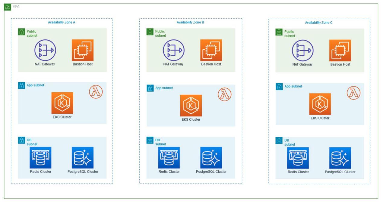
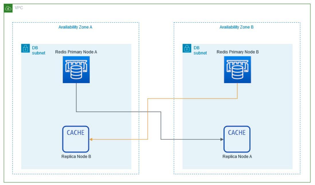
The number of instances to use for the Redis Cluster is defined.
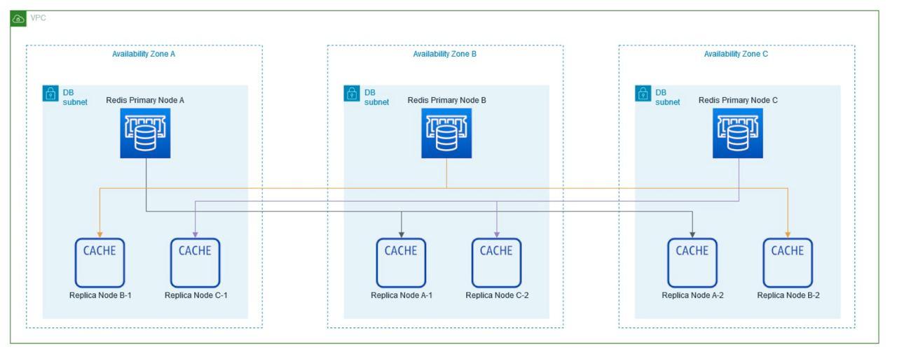
Productive Diagram
Non-Productive Environment Architecture
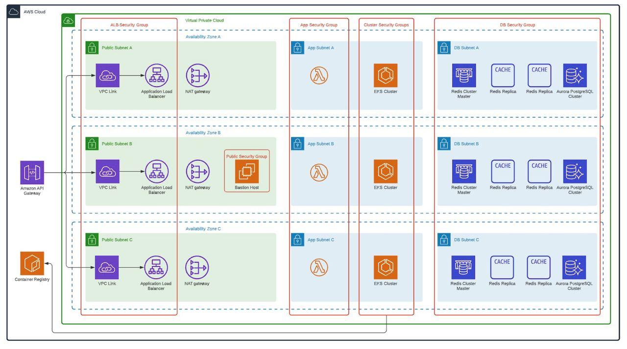
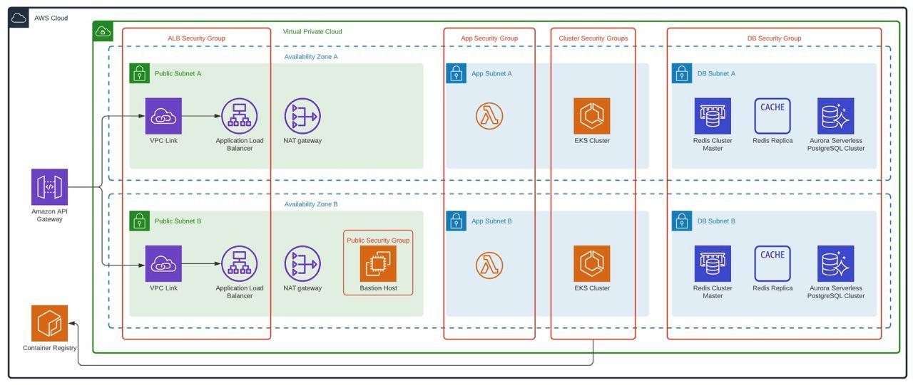
Considering that non-production environments do not require 24/7 use, but if it is necessary that they have at least an architecture similar to that of production, an approved architecture was defined, which allows the different components to be executed in high availability and at the same time allows minimize costs. For this, the following was defined:
- Reduction of availability zones for non-productive environments, remaining in two availability zones (AZ)
- Using Spot Instances to Minimize AWS EKS Worker Costs
- Configuration of off and on of resources for use during business hours.
- Using Aurora Serverless
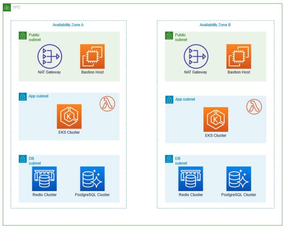
The instances to be used are defined considering that there are only two availability zones, the number of instances for Non-Production environments is simply 4.
Non-production environments diagram
Infrastructure as Code
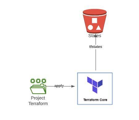
In order to achieve the creation of the architectures in a dynamic way additionally that the environments could be volatile in time, it was defined that the infrastructure must be created by means of code. For this, Terraform was defined as the primary tool to achieve this objective.
As a result of this point, 2 totally variable Terraform projects were created which are capable of creating the architectures shown in the previous point in a matter of minutes, each execution of these projects requires the use of a Bucket S3 to be able to store the states created by Terraform.
Additionally, these projects are executed from Jenkins Pipelines, so the creation of a new environment is completely automated.
Automation and CI / CD Integration for infrastructure and micro-services
Micro-services Deployment in EKS
We helped the financial institution to deploy the micro-services associated with its business solution in the Kubernetes Cluster (AWS EKS), for this, several definitions were made in order to be able to carry out the deployment of these micro-services in an automated way, thus complying with the process Complete DevOps (CI and CD).
Deployment Pipeline
A Jenkins pipeline was created to automatically deploy the micro-services to the EKS cluster.
Tasks executed by the pipeline:

In summary the steps of the pipeline:
- Get micro-service code from Bitbucket
- Compile code
- Create a new image with the package generated in the compilation
- Push image to AWS ECR
- Create Kubernetes manifests
- Apply manifests in EKS
Refinement and definitions and standards to be used on the infrastructure
Image Hardening
For the institution and as for any company, security is critical, for this, an exclusive Docker image was created, which did not have known vulnerabilities or allow the elevation of privileges by applications, this image is used as a basis for micro-services, For this process, the Institution’s Security Area carried out concurrent PenTest until the image did not report known vulnerabilities until then.
AWS EKS configurations
In order to be able to use the EKS clusters more productively, additional configurations were made on it:
- Use of Kyverno: Tool that allows us to create various policies in the cluster to carry out security compliance and good practices on the cluster (https://kyverno.io/)
- Metrics Server installation: This component is installed in order to be able to work with Horizontal Pod Autoscaler in the micro-services later
- X-Ray: The use of X-Ray on the cluster is enabled in order to have better tracking of the use of micro-services
- Cluster Autoscaler: This component is configured in order to have elastic and dynamic scaling over the cluster.
- AWS App Mesh: A proof of concept of the AWS App Mesh service is carried out, using some specific micro-services for this test.
Defining Kubernetes Objects
In Deployment:
- Use of Resources Limit: in order to avoid overflows in the cluster, the first rule to be fulfilled by a micro-service is the definition of the use of memory and CPU resources both for the start of the Pod and the definition of its maximum growth. Client micro-services were categorized according to their use (Low, Medium, High) and each category has default values for these parameters.
- Use of Readiness Probe: It is necessary to avoid loss of service during the deployment of new versions of micro-services, that is why before receiving a load in the cluster they need to perform a test of the micro-service.
- Use of Liveness Probe: Each micro-service to be deployed must have a life test configured that allows checking the behavior of the micro-service
Services
The use of 2 types of Kubernetes Services was defined:
- ClusterIP: For all micro-services that only use communication with other micro-services within the cluster and do not expose APIs to external clients or users.
- NodePort: To be used by services that expose APIs to external clients or users, these services are later exposed via a Network Load Balancer and API Gateway.
ConfigMap / Secrets
Micro-services should bring their customizable settings in Kubernetes secret or configuration files.
Horizontal Pod Autoscaler (HPA)
Each micro-service that needs to be deployed in the EKS cluster requires the use of HPA in order to define the minimum and maximum number of replicas required of it.
The client’s micro-services were categorized according to their use (Low, Medium, High) and each category has a default value of replicas to use.
Stress and Load Testing for AWS and On-Premise Infrastructure
One of the great challenges of this type of architecture (Hybrid) where the backend and core of the business are On-Premise and the Frontend and logic layers are in dynamic elastic clouds, is to define to what extent architecture can be elastic without affecting the On-Premise and legacy services related to the solution.
To solve this challenge, load and stress tests were carried out on the environment, simulating peak business loads and normal loads, this, monitoring was carried out in the different layers related to the complete solution at the AWS level (CloudFront, API Gateway, NLB, EKS, Redis, RDS) at the on-premise ESB, Legacy, Networks and Links level.
As a result of the various tests carried out, it was possible to define the minimum and maximum elasticity limits in AWS, (N ° Worker, N ° Replicas, N ° Instances, Types of Instances, among others), at the On-Premise level (N ° Worker, Bandwidth, etc).
Conclusion
Navigating the labyrinth of hybrid solutions requires more than just technical know-how; it mandates a visionary strategy, a well-defined roadmap, and a commitment to iterative validation.
Our client’s success story underscores the paramount importance of careful planning complemented by consistent execution. A roadmap, while serving as a guiding light, ensures that the course is clear, milestones are defined, and potential challenges are anticipated. But, as with all plans, it’s only as good as its execution. The client’s commitment to stick to the roadmap, while allowing flexibility for real-time adjustments, was a testament to their strategic acumen.
However, sticking to the roadmap isn’t just about meeting technical specifications or ensuring the system performs under duress. In today’s dynamic digital era, users’ interactions with applications are continually evolving. With each new feature introduced and every change in user behavior, the equilibrium of a hybrid system is tested. Our client understood that the stability of such a system doesn’t just rely on its technical backbone but also on the real-world dynamic brought in by its users.
Continuous validation became their mantra. It wasn’t enough to assess the system’s performance in isolation. Instead, they constantly gauged how new features and shifting user patterns influenced the overall health of the hybrid solution. This holistic approach ensured that they didn’t just create a robust technical solution, but a responsive and resilient ecosystem that truly understood and adapted to its users.
In essence, our client’s journey offers valuable insights: A well-charted roadmap, when paired with continuous validation, can drive hybrid solutions to unprecedented heights, accommodating both the technological and human facets of the digital landscape.

